 SolidWorks is a great tool for designing mechanical parts and assemblies, but I find myself using it as a marketing tool fairly often as well. Whether it is needed for proposals, presentations or just visualizing a new project, I’m often asked “can you just make it look real?”. Luckily when using off the shelf components, that can be done pretty quickly by using decals. With a few pictures or graphics ripped from the web, you can apply a decal to a very simple SolidWorks part and add a lot of realism to your renderings or product concepts.
Most of the mentions for decals with SolidWorks is when applying a sticker or company logo to a part or assembly. Sometimes it makes a good temporary option for showing a membrane keypad on a device. But our focus for today isn’t really for aiding in mechanical design – it is simple, almost throwaway, artwork for presentation graphics and visualization. I apologize in advance for the screenshot overload below…
For a quick rundown on applying decals in SolidWorks, you can visit the official link to the DisplayManager > Decals Pane in the online Help system, or visit the more detailed help on Applying Decals.
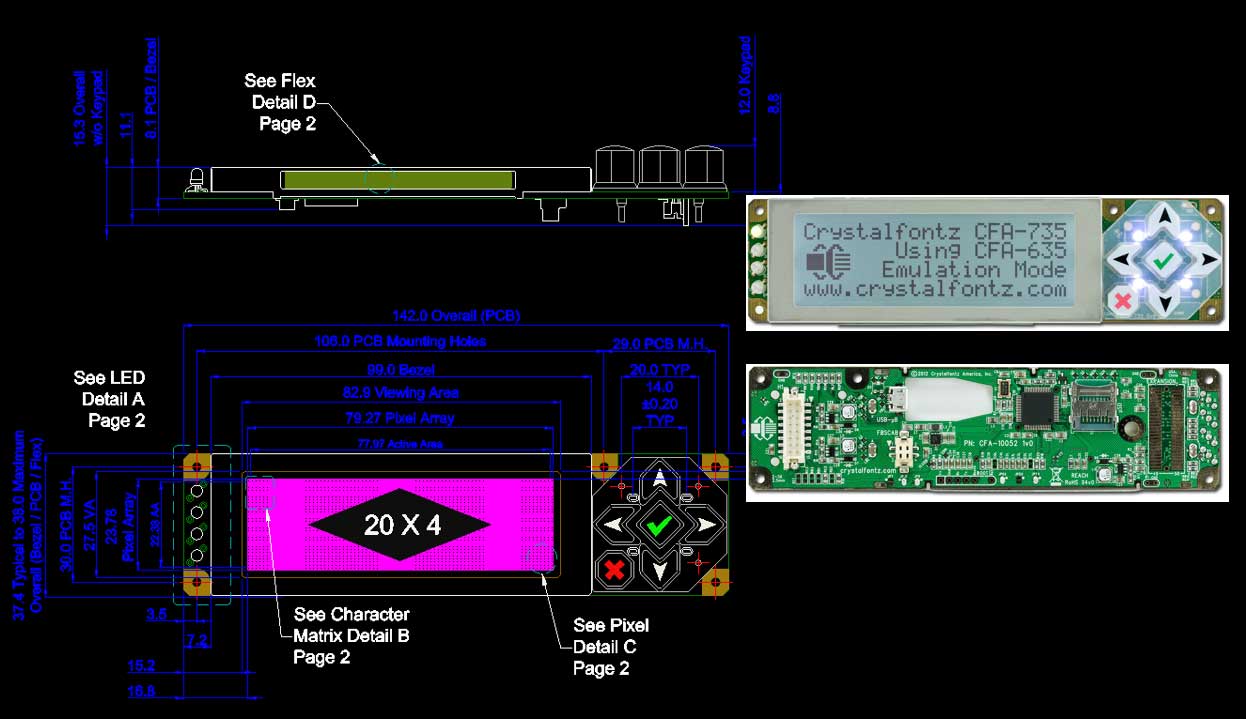
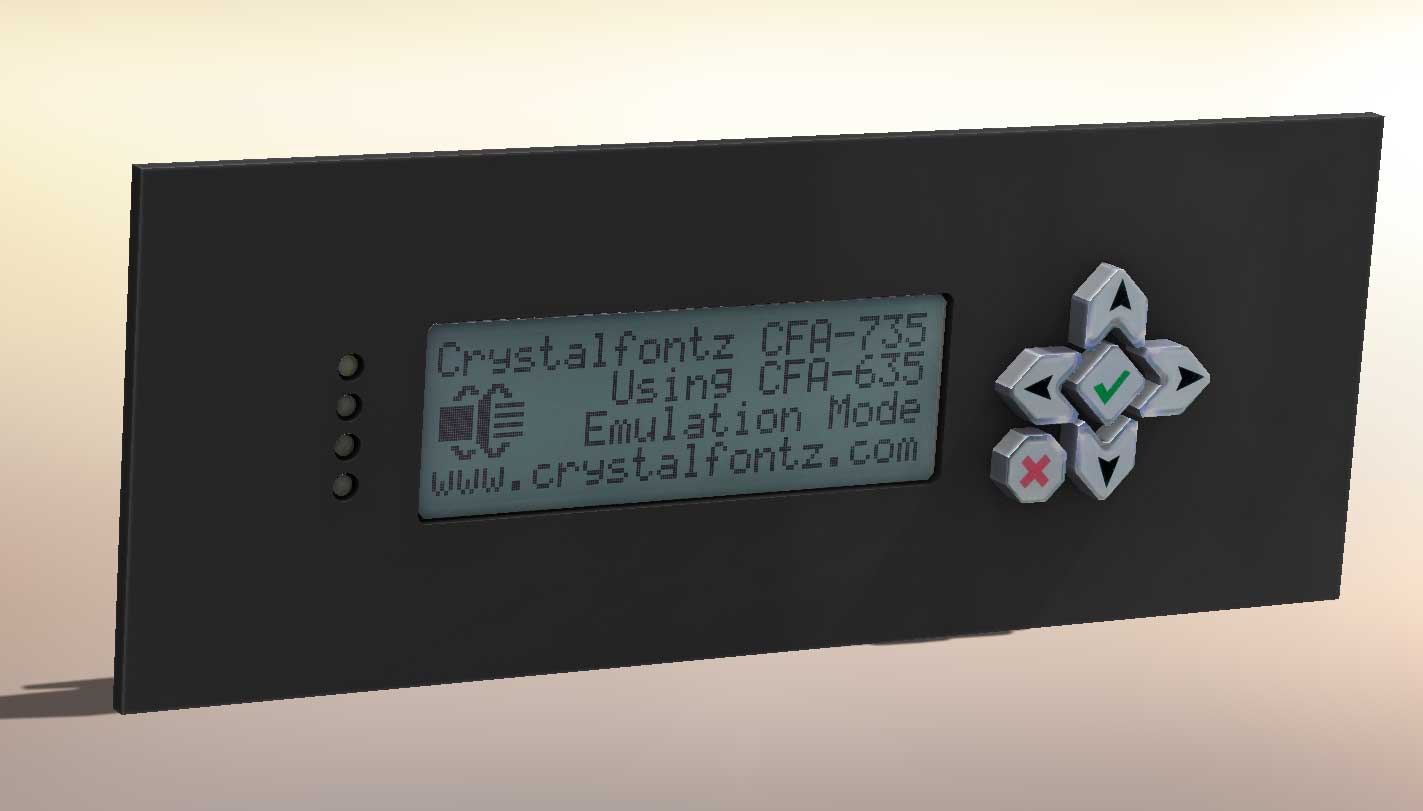
What we’ll do today is take a simple LCD screen with integrated keypad, add a few extrusions, apply some decals, and have it ready for use. The Crystalfontz website has a variety of serial display modules, along with freely available DXF/DWG outlines and photos of the front and back of their products. Perfect for our purposes (and it looks surprisingly similar to the display and keypad on the Digium Switchvox equipment…).
I picked the CFA-735 and downloaded both the 2D CAD and the photos. So these files are our starting point:
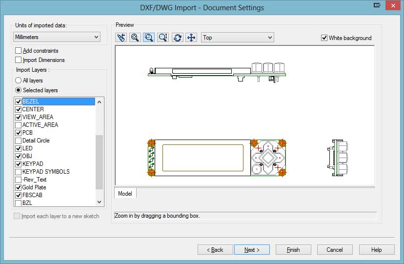
Create a new part and insert the DWG file as a sketch on the Front plane. You can turn off a bunch of the extra layers to speed up this process. All you really need is the outline of the screen, PCB, keypad buttons, and the little LEDs.
I like to create a Block from DWG templates like this so I can keep dropping them into various sketch features and just set all the lines as Construction lines so they don’t affect the final features. You can just trace the parts you care about and extrude them based on the dimensions. After a few minutes and 4 extrusions, the model looks something like this:
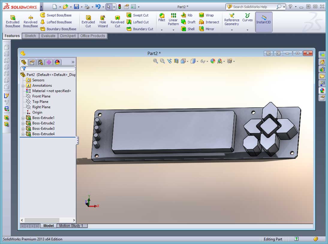
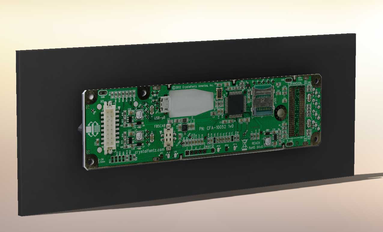
Very simple, and very boring. I didn’t even add any fillets to the edges. I still like the look of 3D CAD parts like this but marketing people don’t share my viewpoint. The next step is to add our first decal. Flip the part around so that you are viewing the flat side of the PCB – this will be a simple first step for applying the decal.
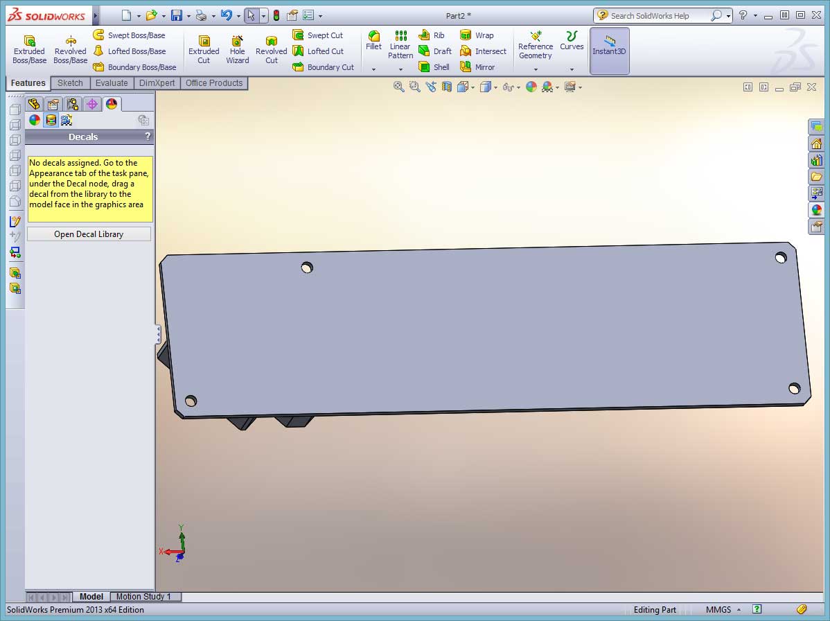
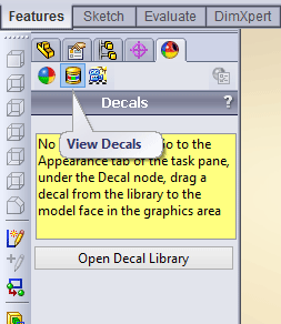
Click the face of the part that will have the PCB decal, and go to the Decals section of the Appearances tab. It isn’t a very obvious little icon:
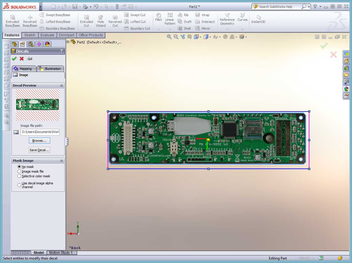
Browse to the file location for the PCB photo that you downloaded previously. Make sure NO MASK is the option selected for the image mask. That is for masking off parts of an image for transparency – we don’t need that on this example. Then just scale the image and move it around until the edges and mounting holes align correctly. The decal should look like this when it is lined up:
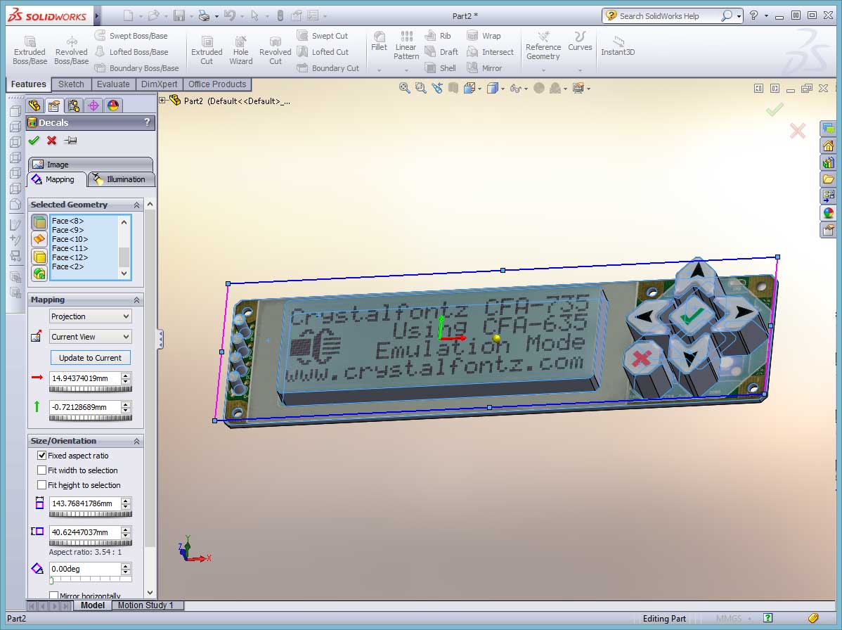
Easy. And it looks pretty cool already. With our newly found confidence in applying decals, lets do the same thing to the front side of the SolidWorks part file. This side has a variety of features extruding from the surface so we can’t just apply the decal with one click without it looking wrong. For this, you’ll need to use the PROJECTION MAPPING type. This will essentially cover the top faces of the extrusions even if they are at different heights. Perfect for what we want to do.
In the Mapping section of the Pane, select Projection as the type and then select each of the top faces. We won’t need to worry about the sides or edges since this was just a top view photo. If you are really into it and have lots of images available, you can project each of the side views as well to get 360 degree coverage. You’ll need to scale the decal image and move around the image until everything lines up properly just as we did before. At this point, the part should look similar to this:

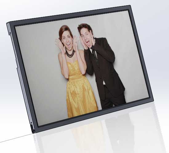
Now we have our simple part with decals applied to the two main sides that you’d see in a rendering. Now we can insert this part file into our next assembly and it will look pretty realistic for marketing use. This is also a pretty easy method for showing simulated screens on an LCD. You can mock up user interfaces of a device and just apply different decals of the screen. Pretty handy for presentation purposes. A side bonus is that the files are still easy to work with inside SolidWorks. PCB assembly files that are “complete” with every little resistor and chip modeled can be a nightmare within even a moderate-sized assembly. This looks pretty realistic even without rendering – these two images are just screenshots with RealView graphics and Shadows turned on with SolidWorks:
So to recap, this isn’t anything earth-shattering from a Mechanical Engineering standpoint. This is however a pretty fast and effective method for adding some realism to product concepts that are still in the early stages or for adding some wow-factor to proposals.
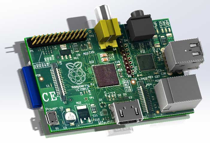
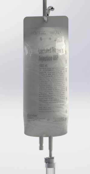
I’ll leave you with a few other examples we’ve used recently.
Raspberry Pi Board:
IV Bag projected onto a curved surface, with some transparency added:
Simulated screen on an LCD: