I finally got another free evening to devote to reverse engineering the Can-Am Spyder diagnostic interface. For the back story, see part 1 here. But things did not quite work out like I hoped for tonight’s Spyder hacking. As usual, it is the hardware guy’s fault.
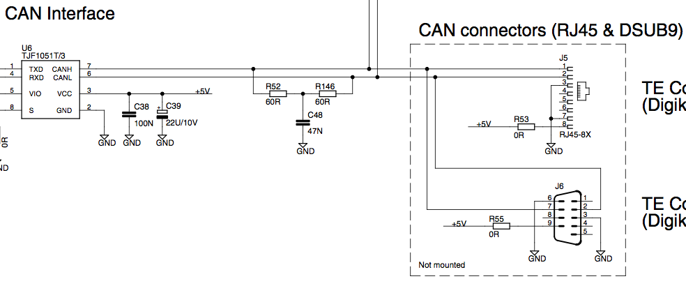
First order of business was to build another cable to connect the CAN lines from the Android Open Accessory kit to the Spyder itself since the Spyder to OBDII effort did not yield anything useful. The AOA board has footprints for both a DSUB-9 and an RJ45 but I used the DSUB connector because I could not find RJ-45 connectors in the lab without magnetics.
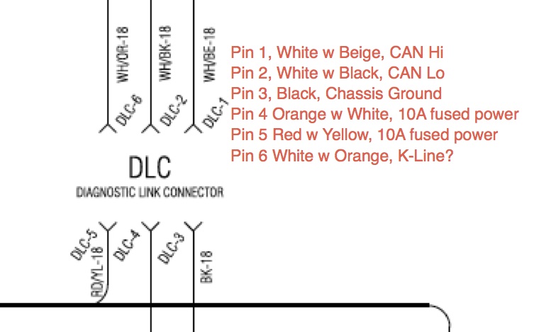
Based on the two schematic snippets, I fabricated a simple 3 wire cable connecting Pin 2 to Pin 2 (Can Low), pin 3 to pin 3 (Ground), and DSUB pin 7 to Deutsch pin 1 (CAN High).
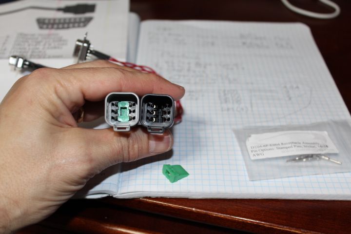
The cable was pretty straightforward to fabricate thanks to the high quality Deutsch connectors. I should have chosen pins for smaller gauge wire but I made these work. See the pictures below for useful tips. Pry the orange weather boots out of the backside of the connectors and thread your wires through the boot before locking them into the housing. The boot makes a convenient way to hold them steady while you beep out the pinout one last time (had to be careful, no pin extraction tool available if I messed up). After the pins lock in place with a satisfying click, the green wedge piece inserts from the front to lock everything in place.

Cable fabrication went smoothly but I was denied the quick and easy path to testing the new cable. The AOA board has an embedded FTDI 232R that the sample projects use as a console output. I had tested the console output and it worked fine on the lightweight web server example. I was hoping to do some simple exploration of baud rate and message count using the time honored printf debugging. But it appears that something in the code for the provided Android Accessory Protocol examples conflicts with the serial console and they refuse to load, debug, or execute when a USB cable is connected to the 232R. It is odd, maybe a power budget issue but I can have a working CAN demo session connected when I connect a USB cable to the FT232R. Connecting the cable is fine but as soon as I open the port, the CAN connection in the demo drops. And it returns immediately when I close the session.
So this Spyder diagnostic hacking session is over. Now I either spend time figuring out the serial console, log all data to internal SD via the FAT FS library, or develop an Android GUI. The Android GUI option is probably the best way to go long term, better bandwidth and faster dev cycle but it will be a steeper initial learning curve. Oh well, I wanted to get better at Android development anyway and this will probably make for an interesting part 3.
Update: After looking at the schematics, I figured out how to enable the serial terminal without disrupting the CAN communications. The two jumpers on JP4 are installed by default. Remove them and you can open the port without triggering a reset of the processor. Spyder Diagnostic Hacking is back on, I can at least figure out the baud rate now.
This was a continuation of a previous post. Click through to see the first post.
9 Responses
HI,
I see you are deep in thought on the very same subject I would like to do. I have a 2009 SE5 that I would like to access also, and limited funds. You are in a much better position with tools at hand to get this done. I am a retired FE GE Medical group. Please keep this project alive, why not use a regular Laptop with a USB to CAN adapter to start? Larry Osborn
Just wanted to pass along some encouragement to keep going to unlock this thing. The nanny is FAR to intrusive and I’d be willing to pay any reasonable price for a map or hack to change the parameters. Just one consumer’s preference: I’d like to be able to adjust it rather than totally defeat it. No question that the ability to get the machine moving around a bit would be desirable. If BMW can offer different ride modes to the rider with their late model machines why can’t BRP?
You should always have RJ45S around or hack a network cable. Be careful connecting a DB 9 (RS232) to anything you don’t know is built for it like a can bus device applying + / – 12 Volts DC to 5Volt only devices tends to make them very un happy! And can cause them to fry. Now do you know that your Spyder side Can Bus still works, and how?
Theme: Can-Am Spyder Diagnostic Hacking 2: Things Don’t Always Follow the Plan
Hey,
i want order some plugs to make my own cable-set. can you give me a web address whrer i can found this plugs?
thank you and best greetings!
Hey,
is there any chance you could share the recorded can bus messages with us? I am currently at the completion of a similar project and you could really help me out with this information.
Thank you very much and best greetings,
Alex
PS.: If you want to my team and me can help you reverse engineering this messages. 😉
Hi I have a nut job stalking me n after she destroyed my 3 cars she got to my Can Am as well recently. Is there a way to reinstall the firmware without going to the dealer?
i have 2019 Can am spyder F3. i need this OBD2 adapter, i found a female 6 pin connector on my bike.
i have checked all over website for this adapter cable but no luck, could not find it even with Amazon.
if someone can help me to get one of this cable i am really appreciated.
IWISS Deutsch DT Connector Kit in 2,3,4,6,8 and 12 Pin Configurations, Size 16 Stamped Contacts, Sealed Automotive Electrical Connectors, 94 Pieces this will have the 6pin plug your looking for you might have to buy a cripper to connect the wires
I have the buds program on my computer. It was a 500 dollar investment. It has a cable that runs through a little box before going to the bike. Have used it 3 times in 3.5 yrs. Has saved me money