National Pipe Thread Taper or NPT threaded pipes and fittings are deployed in a variety of fields where transportation or containment of liquids, gases, steam, or hydraulic fluid is required. The NPT geometry allows internal and external thread surfaces to further engage when torque is applied to the thread assembly. This creates a fluid-tight seal. With NPT, as opposed to NPTF, the use of a sealing compound or tape is typically applied to the threads to complete the seal. Because of NPT’s mating and sealing capabilities, a practical knowledge of the NPT thread is a valuable addition to an engineer’s toolbox.
This quick tutorial will demonstrate how to model NPT threads on SolidWorks. In this example we’ll be modeling a standard pipe, 1-1/2 NPT Pipe Size at 11-1/2 Threads per Inch. Even though we’ll be modeling a standard part in this example, this procedure may also be applied to custom components where the use of an NPT thread is appropriate.
NPT is defined by ANSI/AMSE standard B1.20.1, and in this article we’ll be specifically referencing the ANSI/ASME B1.20.1-1983, including its charts and tables.
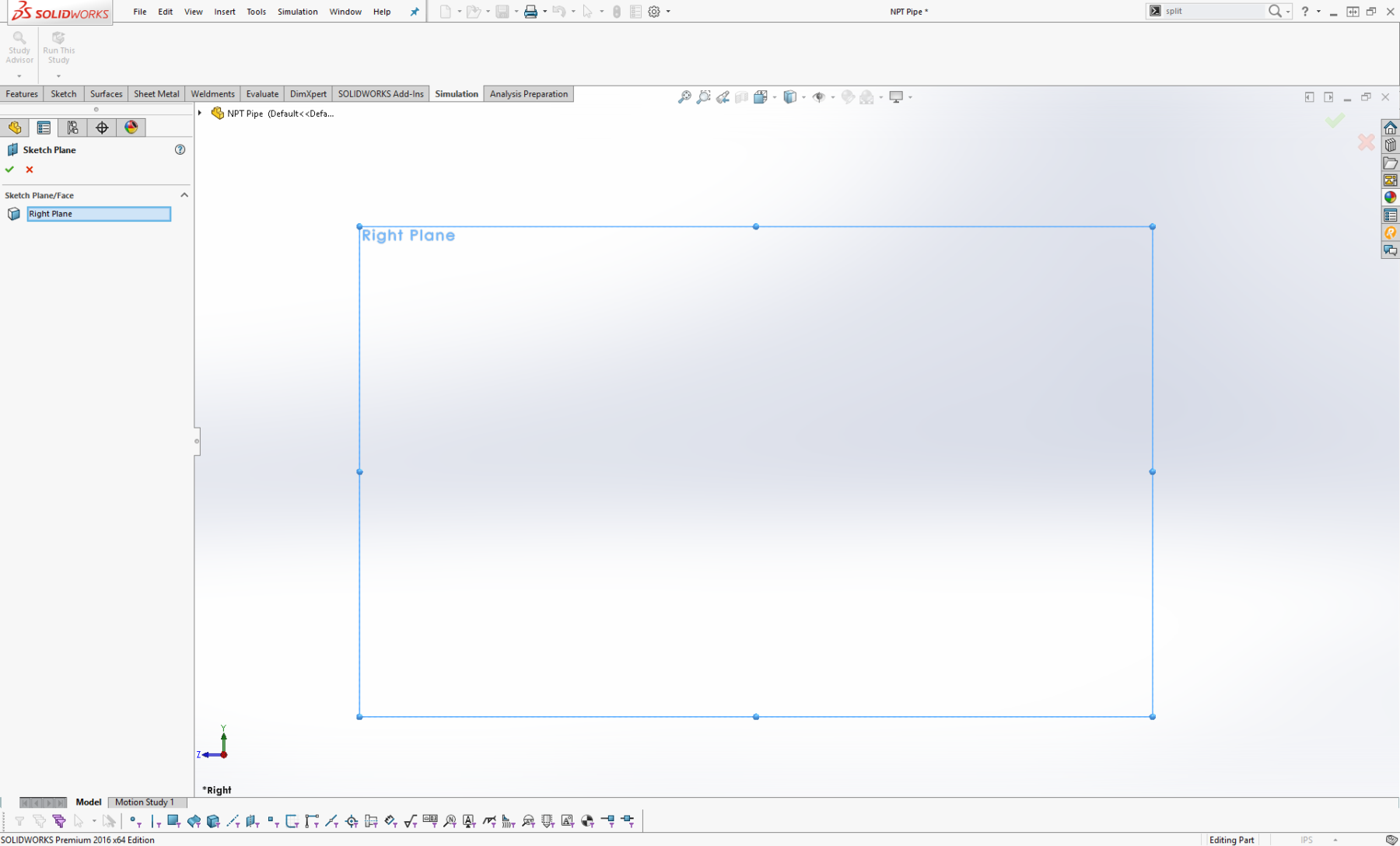
- Create a Sketch on the Right Plane.
- In this sketch draw a reference sketch defining the overall thread parameters.
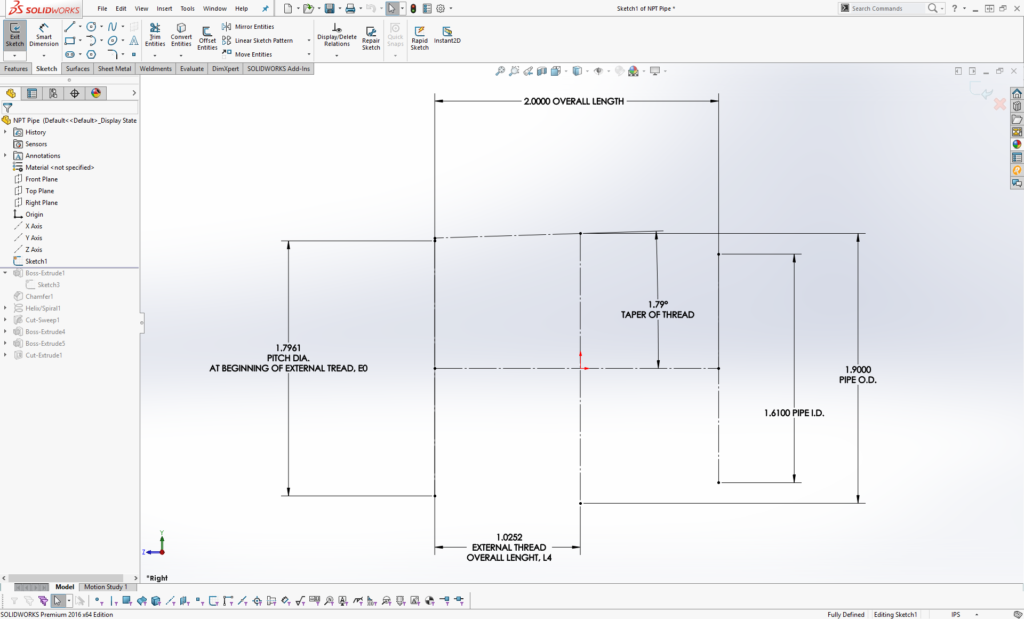
In this example, we are modeling a standard pipe, 1-1/2 NPT Pipe Size, at 11-1/2 Threads per Inch. We will use specific points on this reference sketch to define our pipe.

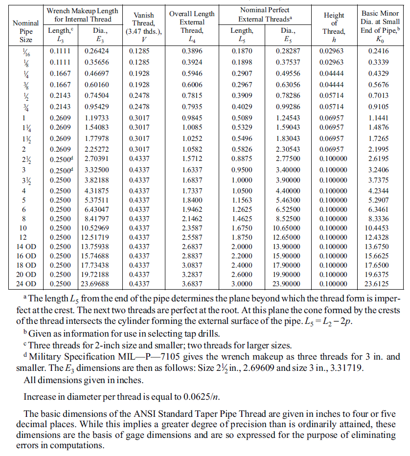
- Define these reference parameters using the table above.
Taper of Thread: The taper on all NPT Thread is 1 in 16, or 0.75” per 1 foot, with the center line bisecting the angle created. The corresponding half-angle of the taper relative to the center line is 1 degree, 47 minutes or 1.79°.
Pitch Diameter, E0: Pitch Diameter at the beginning of the thread.
External Thread Overall Length, L4: External Thread Length
Pipe O.D.: Pipe Outside Diameter
Pipe I.D.: Pipe Inside Diameter (note that Inside Diameters are not listed in the table)
Overall Length: Pipe Overall Length (note that overall length is also not listed in the table)
These values may also be acquired using the formulas contained in the ANSI/ASME B1.20.1. Note that the listed dimensions are in inches and are given to four or five decimal places only to avoid errors in computation, these do not indicate required precision.
To account for tolerance and precision during the fabrication of these threads, refer to guides such as this one, which explains how to use external and internal NPT thread gauges. These go-no-go gauges control quality of NPT threads during fabrication.
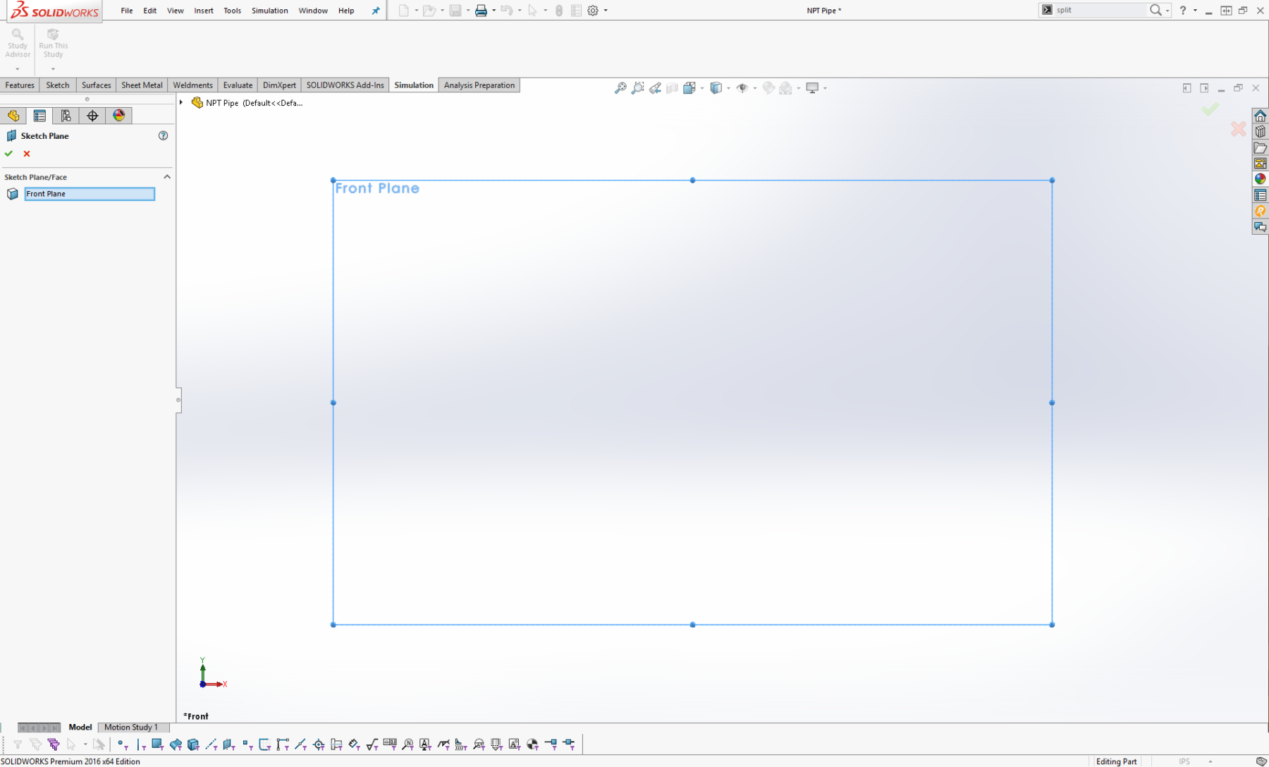
- Create a Sketch on the Front Plane.
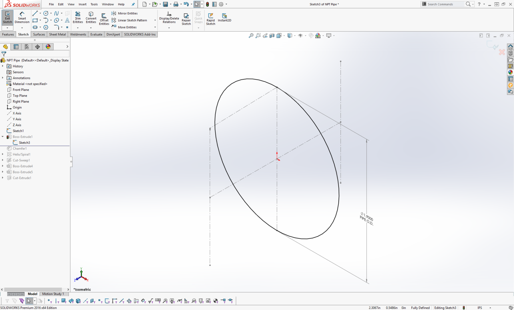
- With this sketch falling on the origin, normal to the central axis, draw a Circle concentric to the origin with a diameter equal to the outer diameter of the pipe.
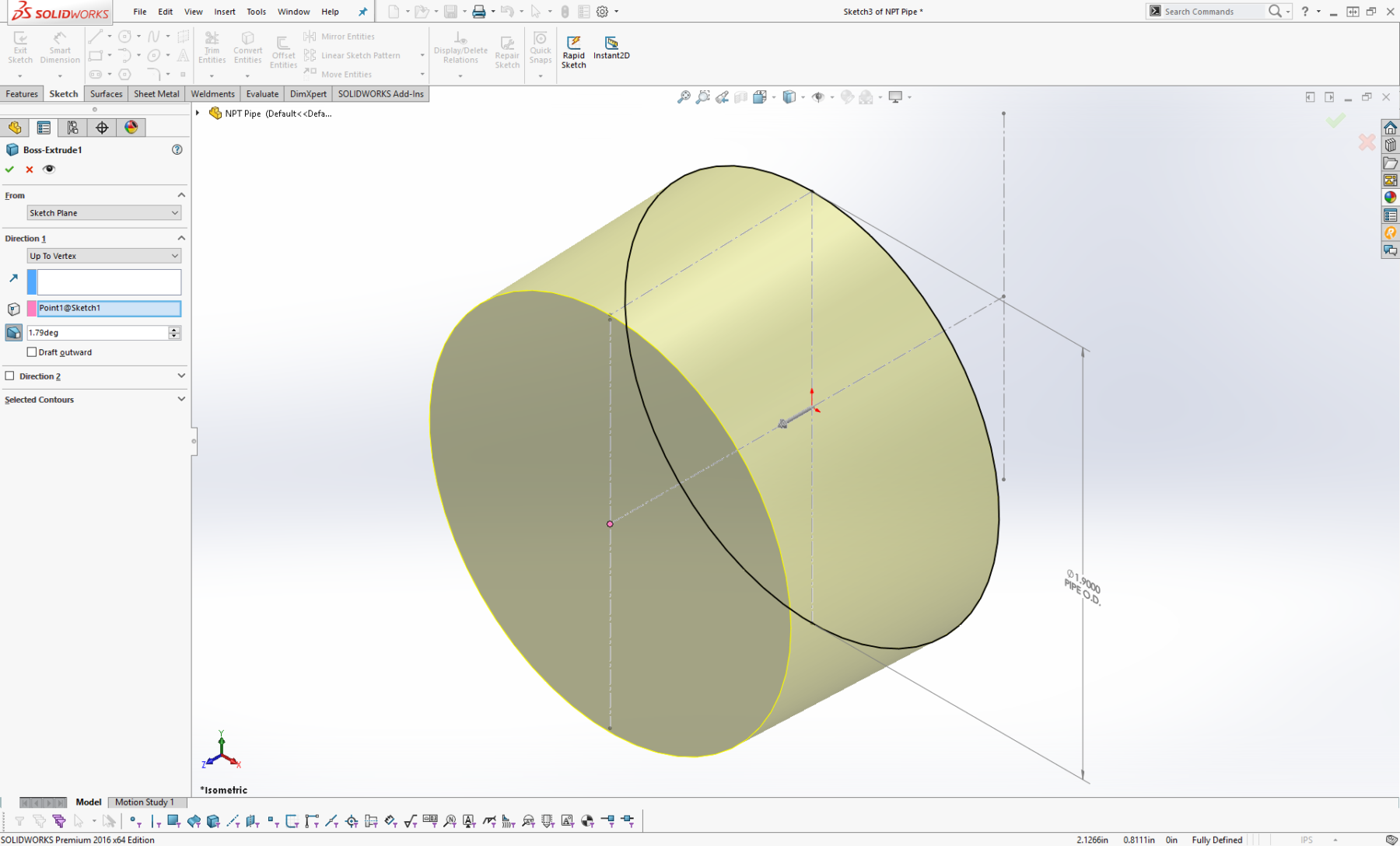
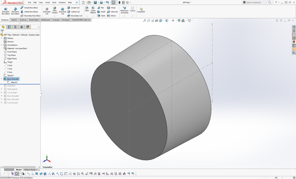
- Boss-Extrude the circle with a 1.79° Taper to the first point on the reference sketch.
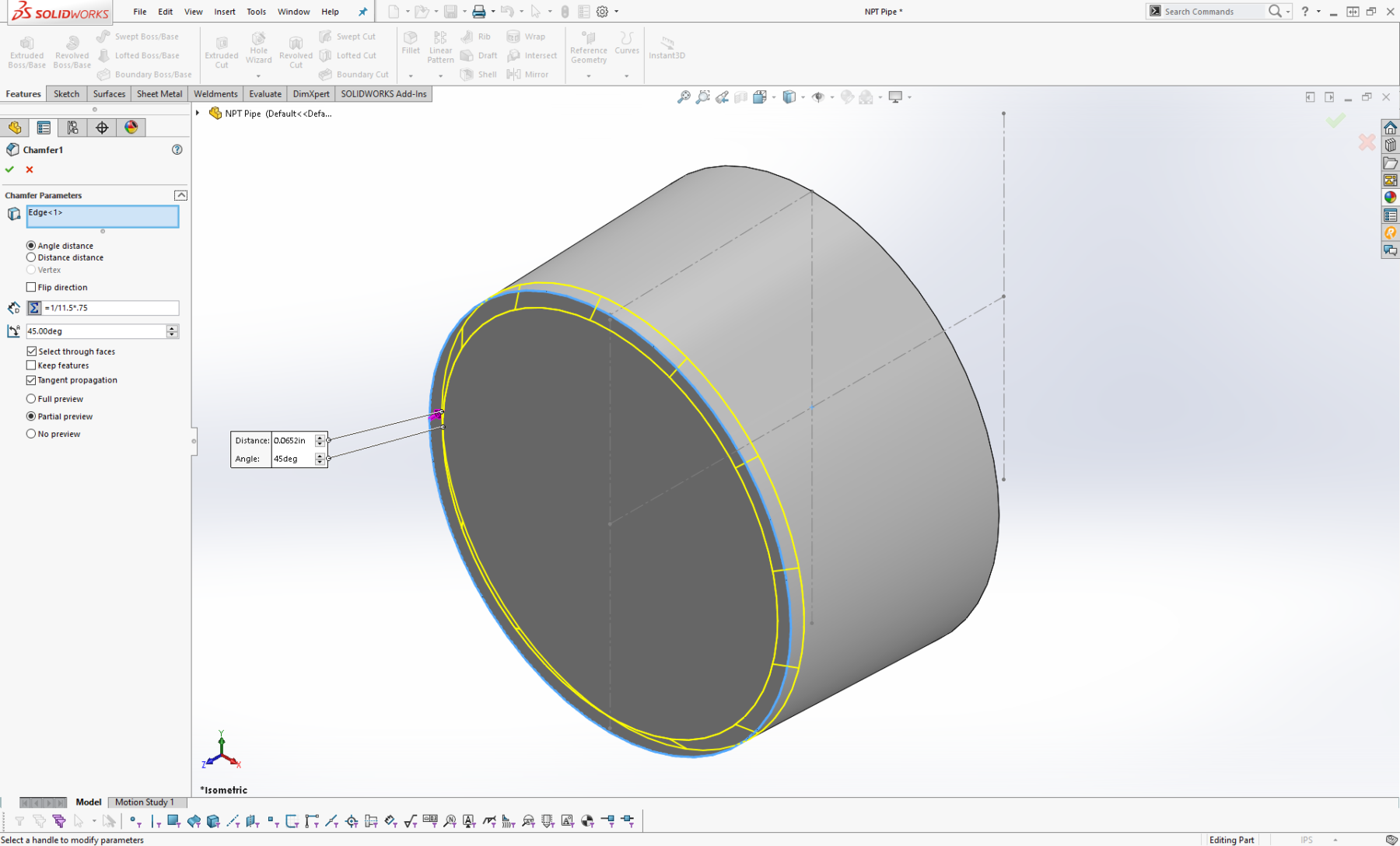

- Chamfer the front face of the extrusion.
In NPT threads chamfers are not required, although a chamfer may be present, there are no specifications on the angle and depth of the chamfer.
For other types of tapered threads such as Aeronautical National External Threads, ANPT, the end must be chamfered 45° with a specified depth define in the ASE AS71051 Standard.
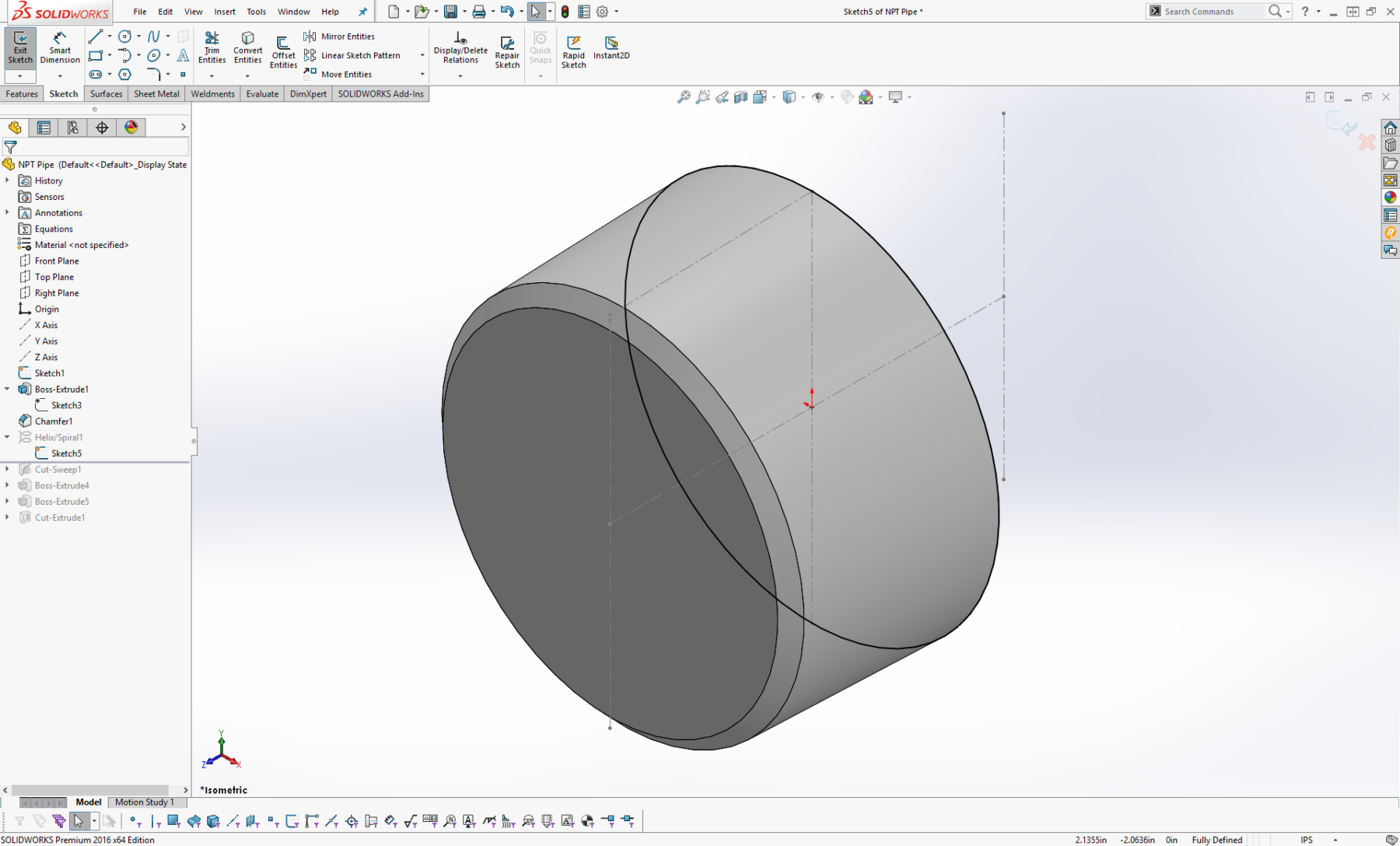
- Create a Sketch on the rear face of the extrusion. Once again, draw a circle equal to the outer diameter of the pipe.
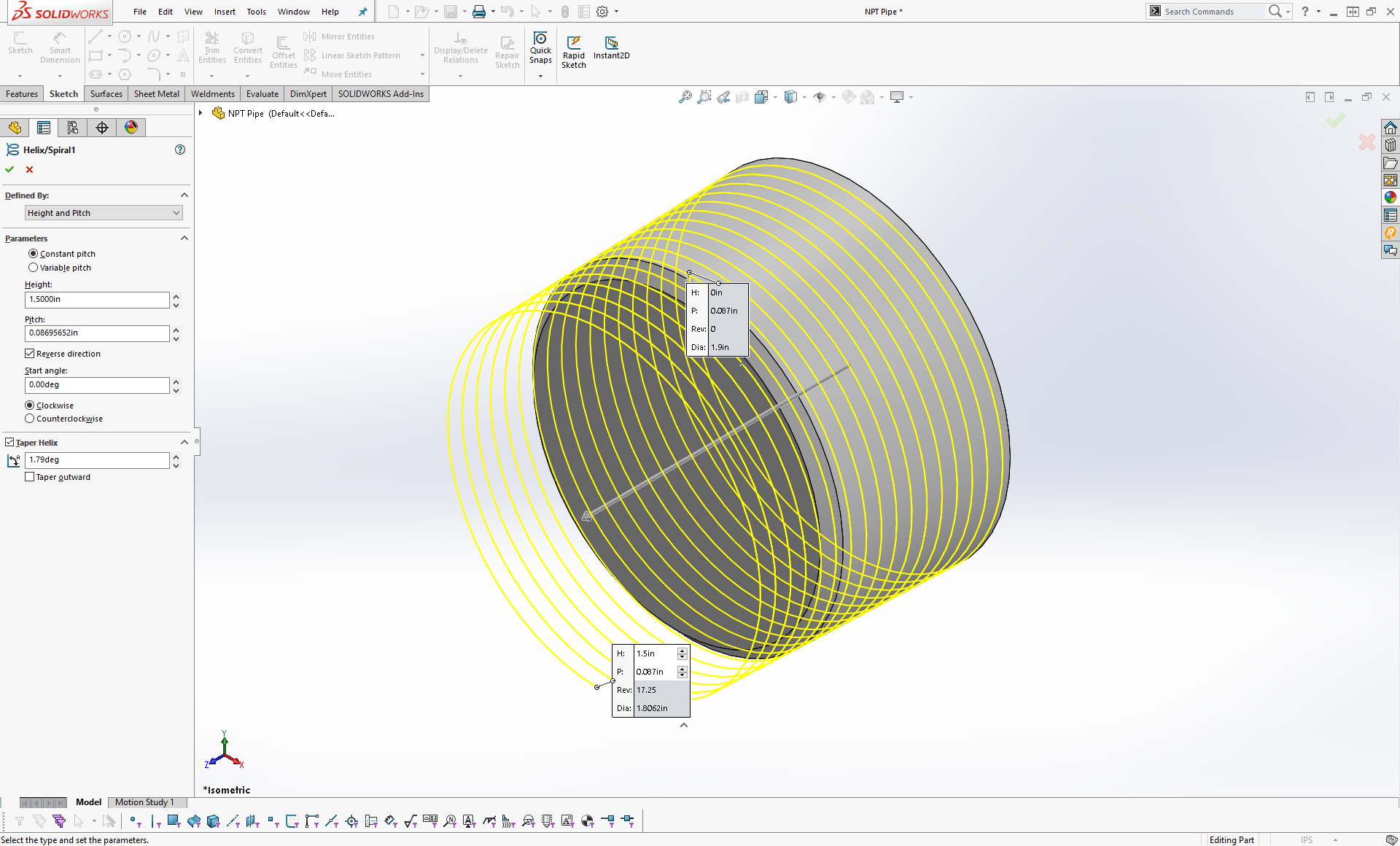
- Create a Helix/Spiral with the following:
External Thread Overall Length, L4: Total length of the external threads, included incomplete threads, or longer just as long as the total thread length is covered.
Pitch, P: Corresponding to the Threads per Inch of the given pipe, e.g. this 1-1/2 NPT Pipe Size at 11-1/2 Threads per Inch will have a pitch of 1÷11-1/2 or .087.
Check “Taper/Helix” and input a 1.79° taper going inwards.
- Create a Sketch on the Right Plane which intersects the helix created. On this sketch we will define the thread profile.
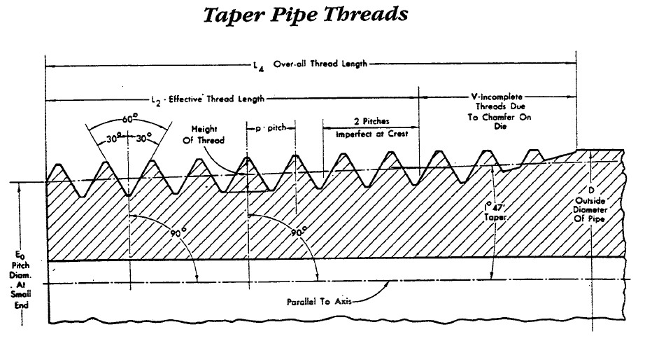
The angle between the sides of the thread is 60° when measured with a line bisecting the angle, perpendicular to the center axis.

Note that in NPT threads, roots and crests of the thread are truncated with a square flat.
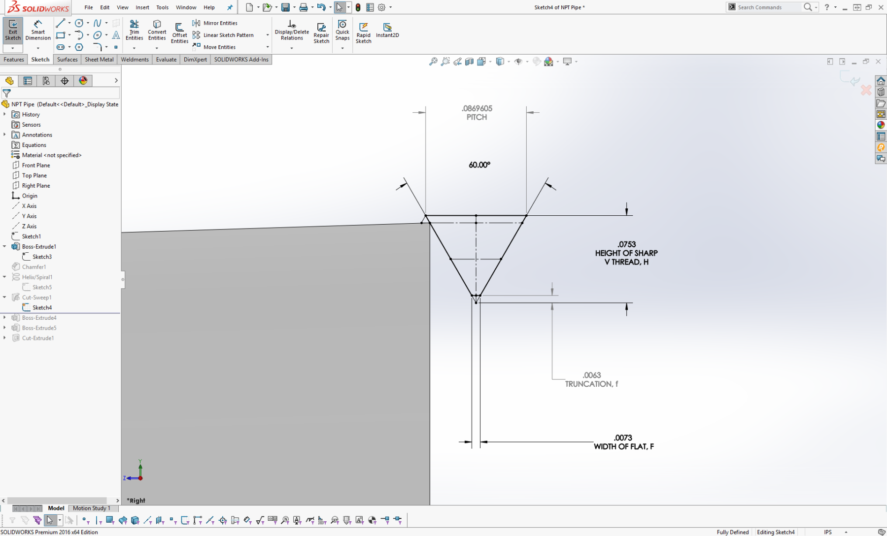
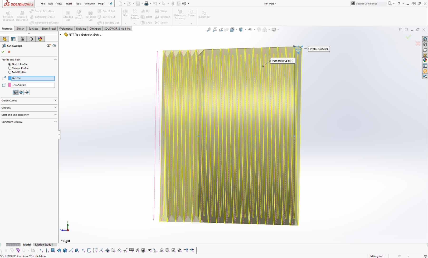
- Use the table below to define the thread profile, this includes:
Pitch, P: Corresponding to the Threads per Inch of the given pipe, e.g. this 1-1/2 NPT Pipe Size at 11-1/2 Threads per Inch will have a pitch of 1÷11-1/2 or .087.
Height of Sharp V Thread, H: Height of fundamental triangle created be thread profile.
Width of Flat, F: Width of the flat caused by truncation, or shortening of the thread crest or root.
Truncation, f: Flattening of thread crest or root.
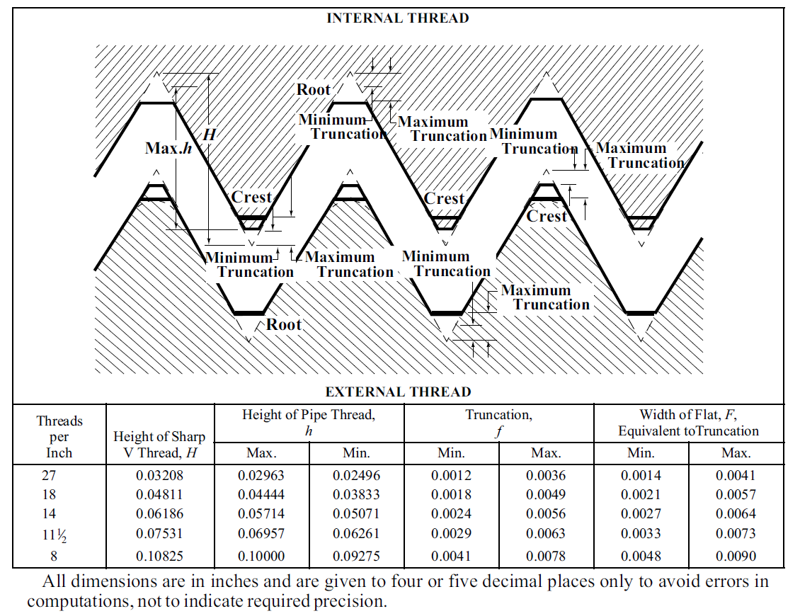
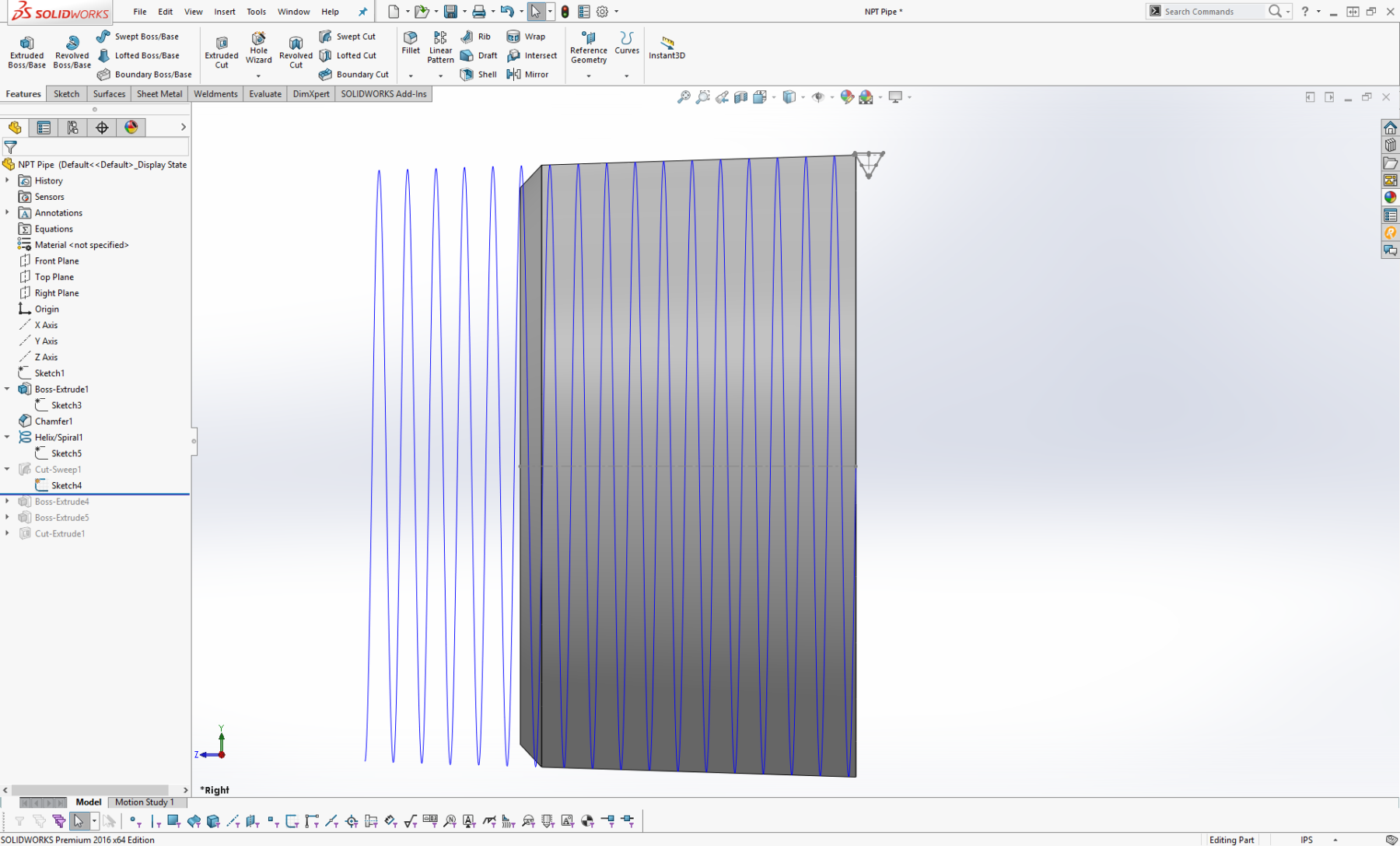
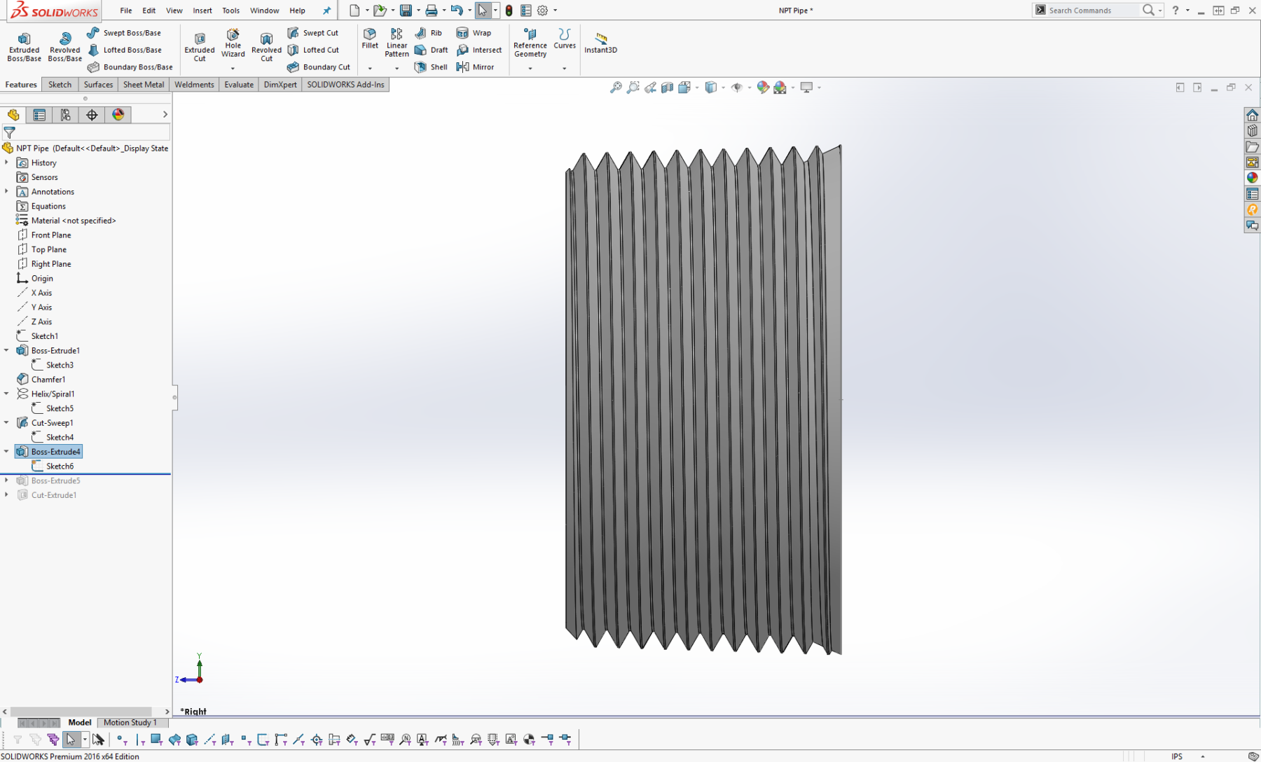
- Cut-Sweep the thread profile about the tapered helix.
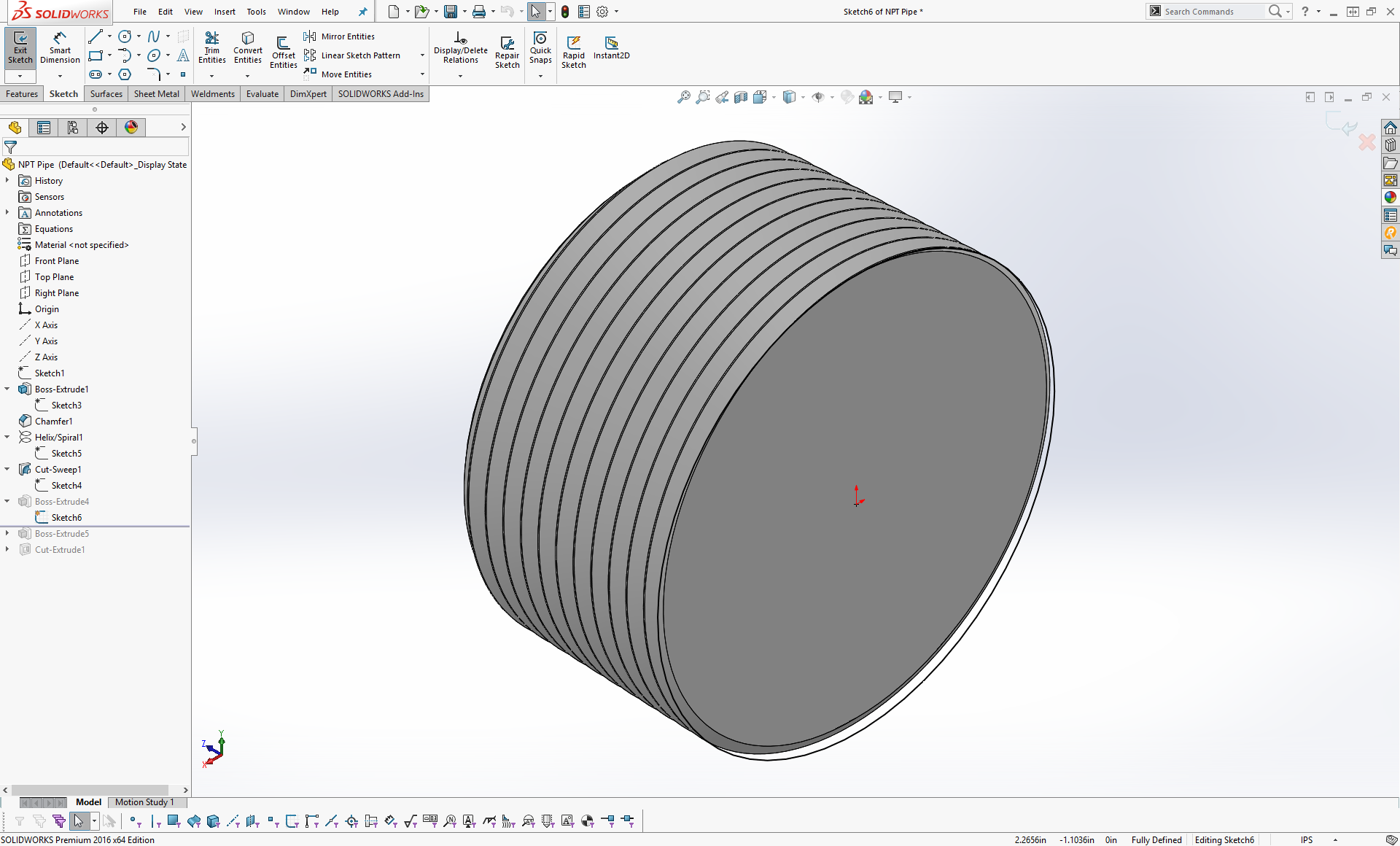
- Create a Sketch on the rear face of the extrusion and draw a circle equal to the outer diameter of the pipe.

- Extrude the circle up to the Front Face of the thread with a 25° taper.
This creates a lead-in chamfer at the end of the thread. This is a result of the chamfer on the die during fabrication, which creates imperfect threads at the and of the thread.

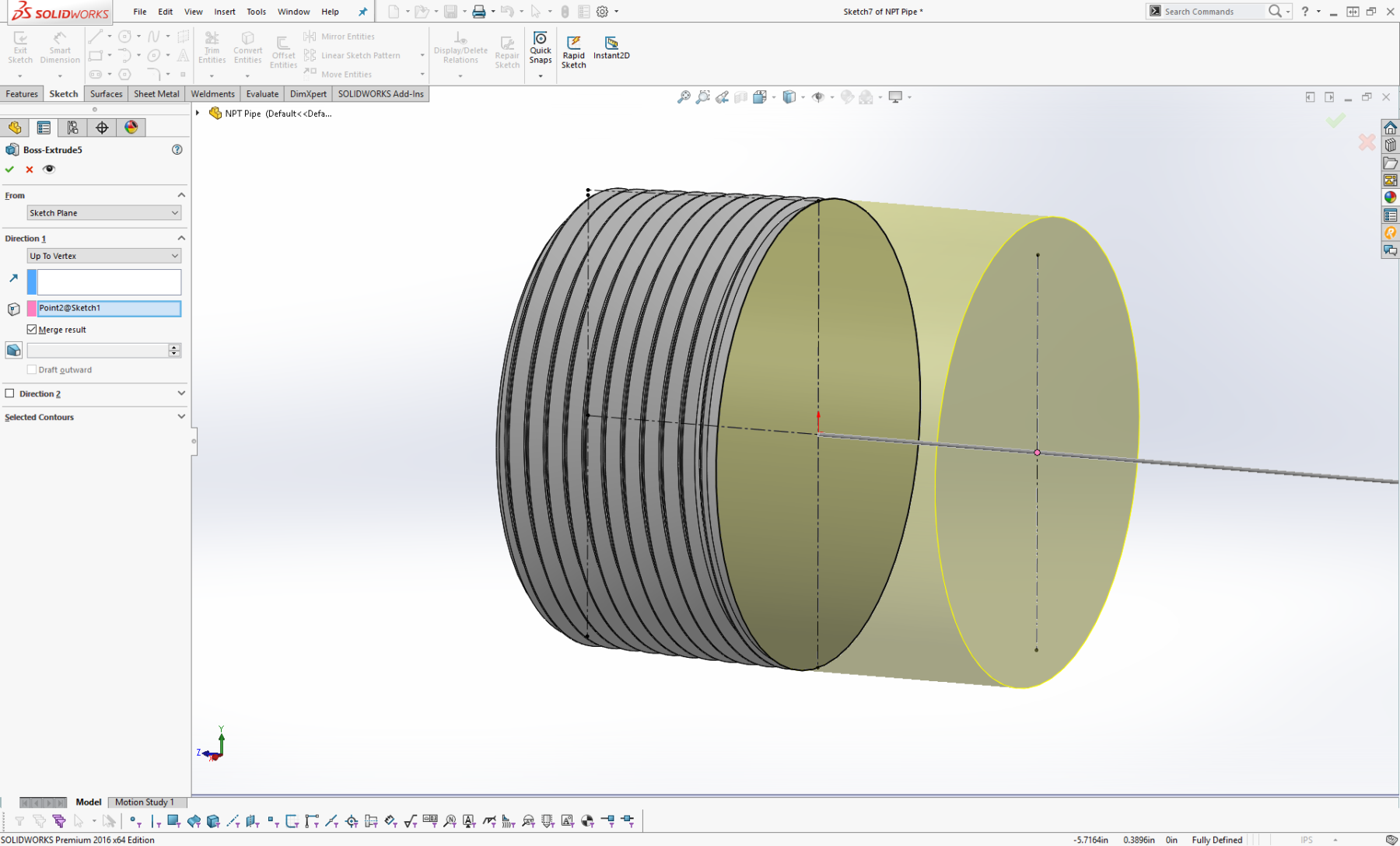
- Create another Sketch on the rear face of the thread and Extrude another circle equal to the outer diameter of the pipe to the third point on the reference sketch.


- Create a Sketch on the new face of this extrusion and draw a Circle equal to the inner diameter of the pipe.

- Cut-Extrude this inner circle through the whole body.
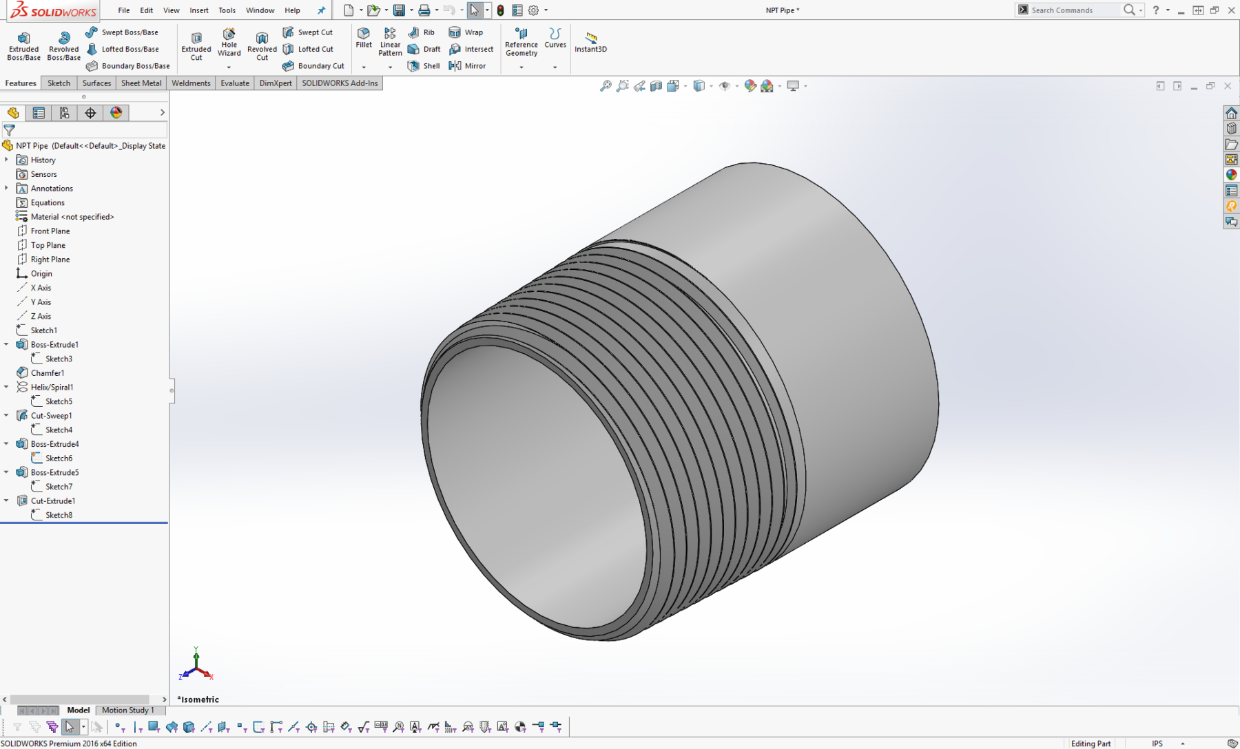 And Done!
4 Responses
Excellent tutorial. I spent hours reading through NPT charts and trying to properly model them in SW. Then I found this site and I followed it exactly. Took about 10 minutes and the threads look perfect. Great, now I can make rapid prototypes with printed pipe threads!
Thank you, glad it was helpful.
can you share hoe to create internal & external NPT thread in solidworks
This tutorial explain how to create external threads. Solidworks has an option in the hole wizard to create internal npt threads, under tapered threads.