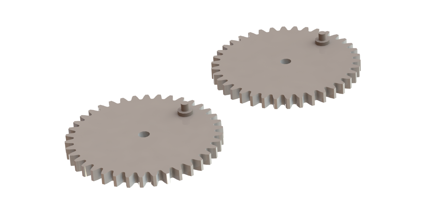
Here at Sparx Engineering, we utilize a variety of fabrication techniques to take conceptual ideas and create actual working prototypes. The ability to quickly and readily fabricate functional proofs is vital in our work. It allows us to confirm ideas and possible solutions to the design problems that come along. Recently, we’ve started exploring the application of resin casting to create prototype components. In this series to demonstrate resin casting, we created a pair of gears. Each gear, once cast-ed was assembled to engage the other to form a simple rotary mechanism that transmitted torque.
Casting itself is not a new concept, in fact casting is commonly used in model making and prop replicas. Life-like alien heads or realistic looking guns and swords are commonly made for movies using different casting methods. With casting, high quality parts can be produced with great repeat-ability and reliability. Its these benefits that makes casting such a useful tool in an engineers toolbox.

For instance, casting may be used in producing parts like the complex shell to the right. A mold made from this shell can be used to produce duplicates that retain the shell’s complexity and detail. As you can see, features such as the shell’s numerous ridges, imperfections, and undercuts are effectively picked up by the mold.
In our application, we adapted this same flexibility. This fluidity that works so well with organic and irregularly shaped forms was also used to produce geometrically precise, straight, and predictable parts. We achieved this through strict material selection and careful machining practices.
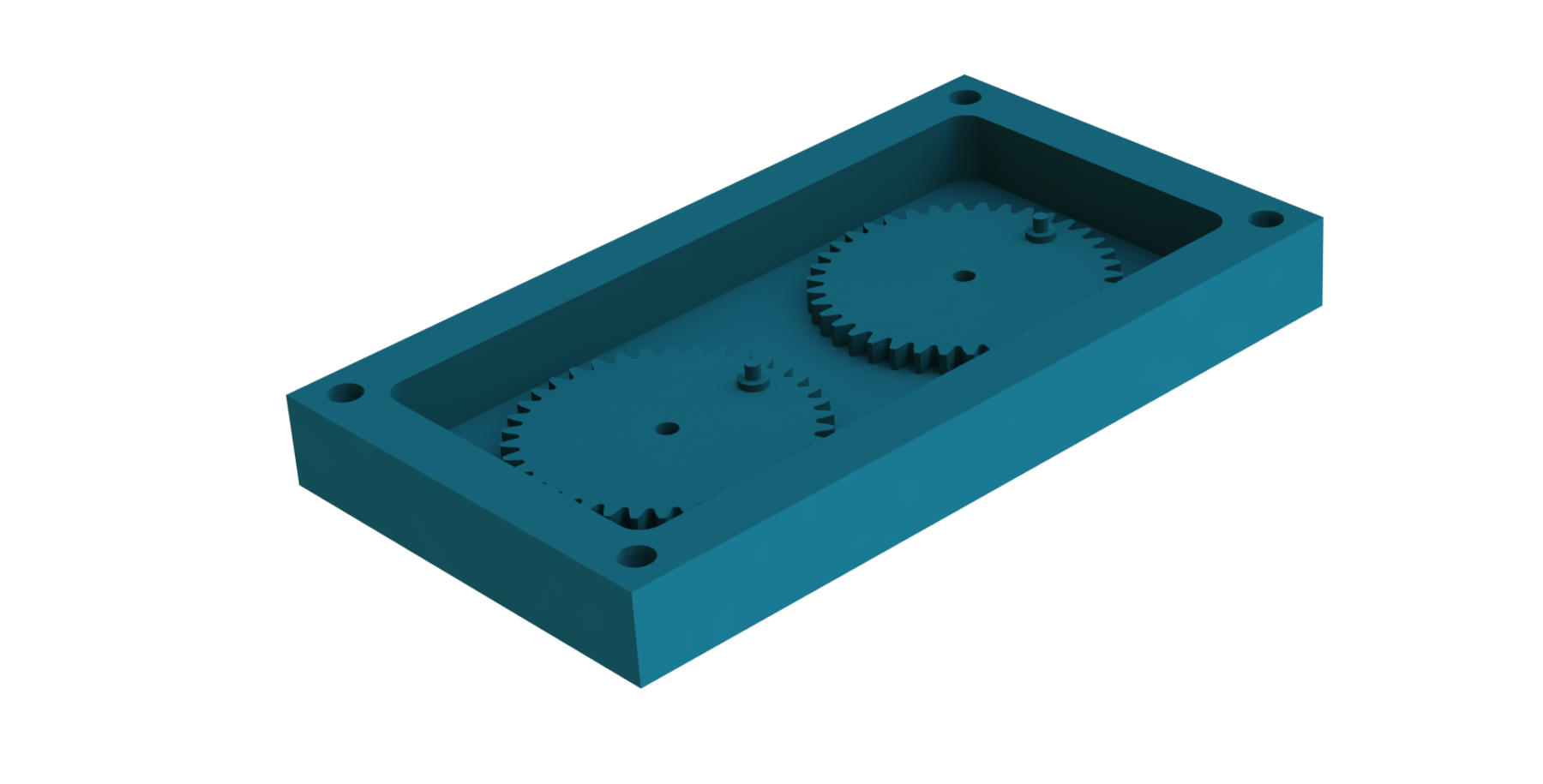
In this first part, we will cover the creation of the mold pattern, which is essentially a pattern for the silicone mold in which the final part will be produced from. This mold pattern, shown below, was milled using our CNC Mill (Roland MDX 540) out of RenShape 460 material, a modeling and styling board which is an awesome material for this application because of its performance characteristics which includes: ease of machining, excellent dimensional stability, good edge definition and low levels of residual particles for easy clean up.
If you would like to know more information about RenShape 460, along with a list of other materials available with similar properties, see this guide by Michal Zalewski. This guide is a valuable source of information that goes more in depth on details involving material selection, fabrication basics, casting in general etc.
Part I of this series is specific to projects relying on CNC milling, so if you are interested in replicating hand made or 3D printed parts, you may want to wait till the next parts of this series. Alternatively, this site provides a good overview on how to build patterns by hand.
Otherwise, lets begin!
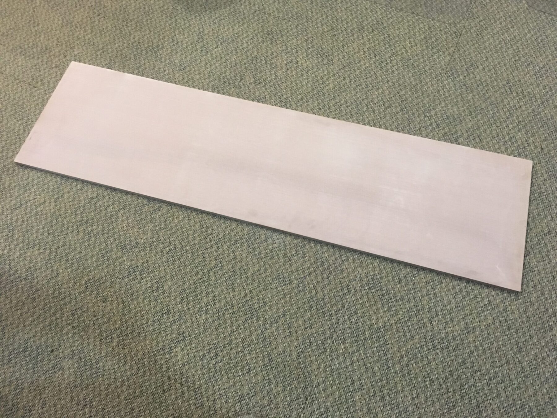
The Renshape 460 material (item #075229) may be purchased online from Freeman Manufacturing & Supply Company. We purchased this piece which was a 1″ thick, 20″ x 60″ panel, shown above. Alternative materials are also listed under Michal Zalewski’s guide.
From first impressions, considering the overall bulk of the piece, we were surprised by how light weight the material was. Prepping the small block below on the band saw, we were very impressed with how easy this stuff cut as well. The smooth and clean surface left behind by the blade was promising and made us even more curious about how this stuff would actually cut on the mill.

The stock material was prepared to a size, roughly 3″ by 1.5″, using a band-saw and mounting holes were added.
Our go-to fixturing method for simple, 2-dimensional milling operations like this are MDF boards. Using the mounting holes drilled into the stock piece we screwed the part down onto our MDF bed. The stock piece’s center was also marked by hand with a sharpie. When model files are imported in to the CNC mill’s proprietary programming software, SRP player, the origin is automatically identified to be the top center of the stock. This reference is used to generate the tool paths.

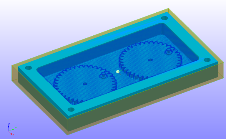
After setting up the stock material, using a 1/8″ square end mill, we ran a roughing pass to cut away a bulk of the material quickly. The blue lines shown below represent the roughing tool path, during the removal of material the end mill will follow these lines.

During the roughing pass adequate clearance was provided for the end mill to fit into tight spaces in the part. In the picture below we see that the 1/8″ square end mill fit in between and around the gear features, but not between the gear teeth.
This next end mill was a 1/32″ diameter square mill, which we used to machine the finer details of the gear teeth.
This 1/32″ square end mill was used to run the finishing pass shown below. Here you can see that the 1/32″ only ran along the surface of the features where the roughing pass left only a little bit of material.
The finishing pass took slightly longer than the roughing pass. Small incremental steps in between cuts ensured a nice surface finish. Slow and steady feeds also minimized the risk of breaking the tiny end mill. The ease of machine-ability of the Renshape material was helpful in this stage to minimize the risk of tool breakage, and eliminate possibility of chatter which resulted in an even better surface finish. It’s important to note that the surface finish generated in this stage of the casting process will carry on to our final product since casting will pick up even the most minor details in the mold.

Below is the finished pattern. Notice the surface finish and sharp edges, this will carry on nicely to the final casted part.

Machining the Renshape 460 material produces very fine particles. These particles must be cleaned off the part before we can go forward with Part II, where we will pour silicone into this pattern to create our mold. The use of air along with a soft bristle brush is very helpful in eliminating these small particles.

Effort invested on the front end of making the mold pattern will pay off once the final parts are casted. Casting will pick up even minor imperfections or dust in the mold pattern, but luckily Renshape is a pretty forgiving material. In the next part of this series, we’ll fill this pattern with silicone in order to create the actual mold that we’ll use to form the gear components. Stay tuned!

2 Responses
The molding material should be well selected to meet the applications’ physical and chemical requests. If the material is corrosive or volatile, it will increase the mold fabrication and maintenance costs.
What material are the hold down screws made of? They look metallic?